.svg "bes-logo (1)")
By Ryan M Welsh, Sr. Mechanical Engineer, and Brett Goldfarb, Mechanical Engineer
By Ryan M Welsh, Sr. Mechanical Engineer, and Brett Goldfarb, Mechanical Engineer
If you’ve read BES’s previous posts on injection molding (here), you probably know about the importance of draft angles for injection molding—they’re kind of a big deal. In order to avoid plastic parts getting stuck in their molds during production, we add draft angles to all walls surfaces that would otherwise be parallel to the direction of the mold action (the pull-release).
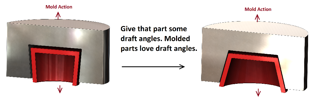
Though this seems straightforward (no 90 degree angles, right?), draft angles have a lot more complexity than just “add them for easy molding.” Let’s delve into it a bit!
Textures—Because Smooth Surfaces are Boring
Most molded parts that aren’t lenses or mirrors will require some texture. Near-perfectly smooth surfaces (the mirror finishes) can get expensive and often don’t provide the right aesthetics or ergonomics. A part might require a deep texture for grip or a textured surface to hide typical wear-and-tear. The deeper the texture desired, the greater the draft angle required. A great rule of thumb for design: 1.5 degrees of draft for every 0.001in of texture depth (or 1.5 degrees for every 0.025mm, if you’re down with the metric system).
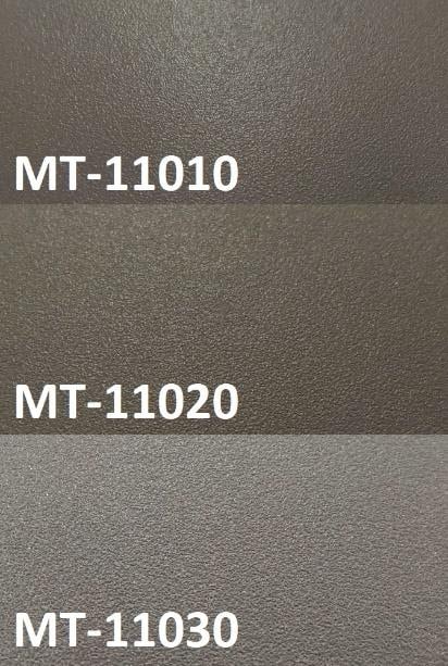
For example, these are some common textures from MoldTech:
MT-11010, 0.001in deep, requires 1.5 degrees of draft or more;
MT-11020, at 0.0015in deep, requires 2.25 degrees of draft or more;
MT-11030, at 0.002in deep, requires 3 degrees of draft—and mold-makers might request even more.
Some deeper pattern-style textures have up to 0.007in of depth, which requires 10.5 degrees of draft! This means that the cup shown in our first figure would need a 21 degree opening to accommodate the 0.007in texture depth!
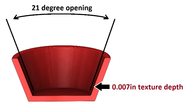
If you planned for only a 5 degree opening early in your design, this could make for a sore realization.
Although a 0.007in texture is extreme, it outlines the importance of being aware of desired textures before delving into engineering type design work. Of course, this also means that it is beneficial to have engineering involved during the initial concepting and industrial design phase as well. You don’t want to find out that your nice vertical features might require a very visible 10 degree draft angle too late in the game.
Mold Drafts—the Unseen Surfaces
Besides the part’s surfaces that a customer can see, there are plenty of unseen surfaces involved in production that are just as important: the mold surfaces. A designer must plan for draft angles in the mold itself—these are features that aren’t visible in the final part at all. It’s a bit tricky but not as complicated as it sounds.
Just as mold tools don’t like to rub on the plastic parts they produce, molds don’t like to rub against themselves. There are often places in a tool where the core and cavity parts of the tool interact. These are referred to as mold “shutoffs”. At these places, the flow of plastic is shut off from the rest of the mold and a hole or cavity is left in the part. Snap-fits are an extremely common plastic feature where mold shutoffs are employed to deal with undercuts.
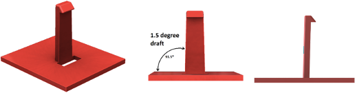
A common snap fit with 1.5 degree drafted sides. The hole under the snap feature allows for the overhang to be formed by the core/bottom side of the mold.
The snap feature shown above is very moldable and has a light, 0.001in deep texture. There shouldn’t be any issues with ejecting the mold or scratching the part surface. However, note that the hole under the snap fit is significantly larger than its snap base. Why is this?
If we matched the mold with the snap-fit, we’d get a core that looks something like this:
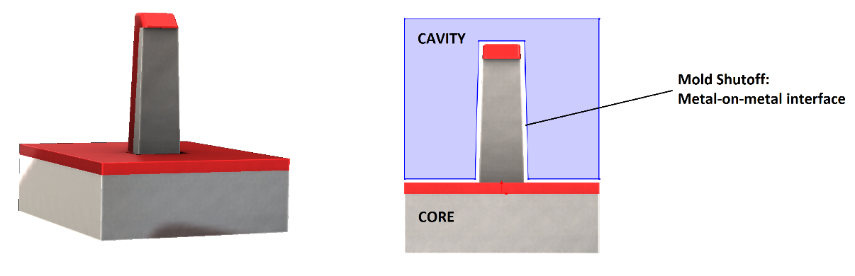
This mold would be fine if we were only making a few parts with our mold. For a $10,000+ tool, let’s hope that we’re making more than a few parts! With a low draft angle at the shutoff interface, we’ll see a lot of friction between the mold cavity and the mold core that would wear the mold too quickly. To adjust for this, we want to aim for around 3-5 degrees of draft at the shutoff interface. You can use a lower angle, but 3 degrees is considered a “nice” value for soft tools and production molds; 5 degrees is great.
For the example above, this means that the core should look more like this:
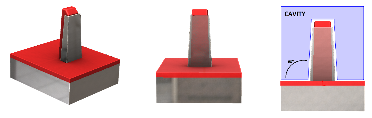
Here, the oversized hole at the base of the snap-fit allows the mold-maker to use a 3 degree draft on the shutoff feature. Even though the light texture of the plastic doesn’t need a 3 degree, the design needs to accommodate the unseen mold requirement.

Not designed for shutoff - Well designed for mold shutoff
A lot of the design constraints imposed by drafts, desired textures, and mold interfaces can be accounted for in the planning phase. The nitty gritty details come into play, however, when the design is nearly complete.
Final Part Evaluation—Draft Analysis and DFM
On top of the planning that should be done before a formal design is considered, there is also a fair amount of nuance in the final design-for-manufacture (DFM). The final DFM step, before a product is submitted to a manufacturer, can result in some very small but important draft features.
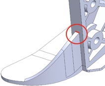
Below is an example of a part where complex parting lines exist due to the nature of the part and required three-way mold action. In this case, extra attention is required for draft angle placement.
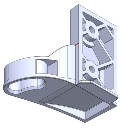
The nearly finalized part is shown here. Note the presence of a parting line (highlighted red) on the long skinny face.
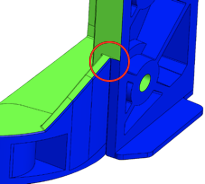
Because this part was designed for a more complex mold tool, expecting three different directions of pull, draft has been accounted for in three orthogonal directions.
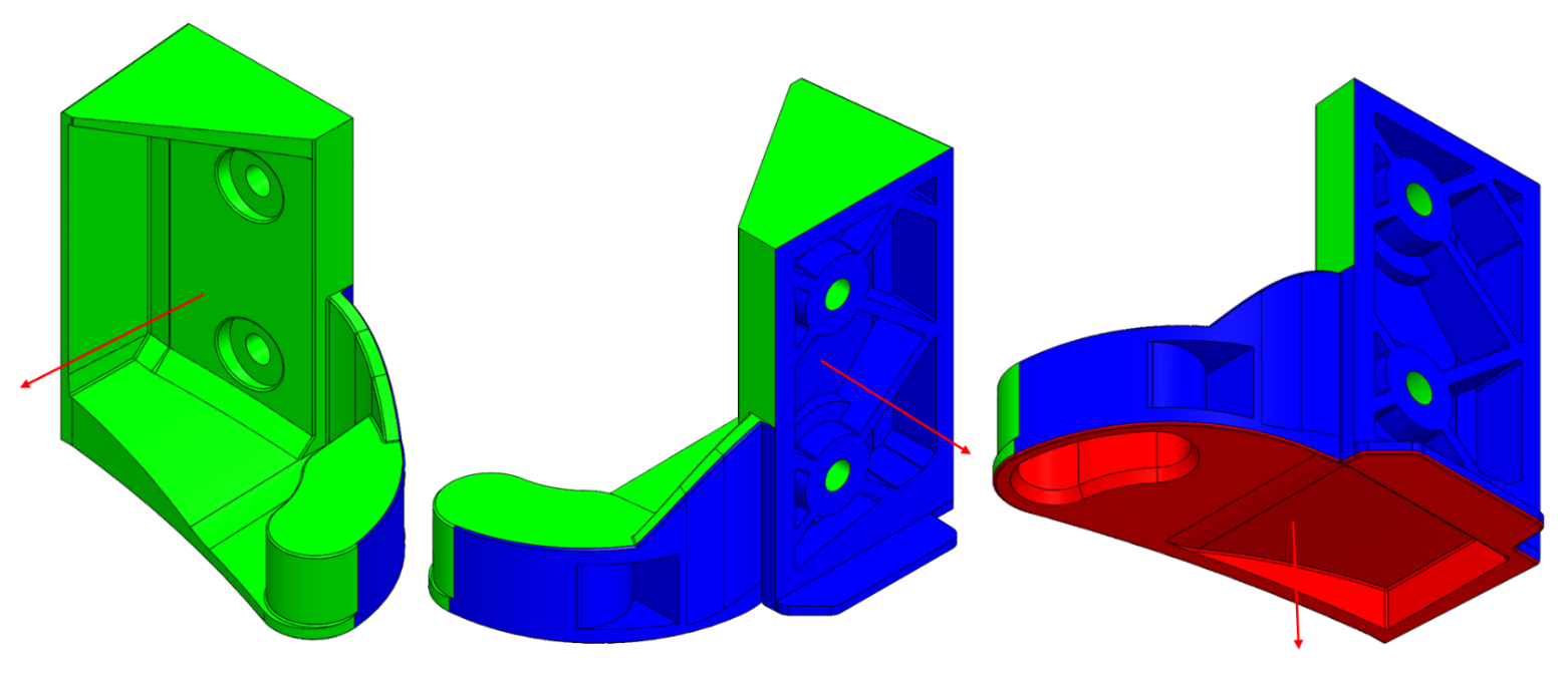
The 3 parts of the mold tool pull in orthogonal directions. The corresponding faces are shown here in green, red, and blue. The area we will focus on is the interface between the green and blue faces and their opposing draft angles.
Further up in the design process, it might not be immediately obvious where to put the parting line for the drafts in the area indicated below. On this part, there is separating rib running into a wall, so the wall needs to be drafted in two different directions or else an extreme undercut will be created—the mold maker will not be pleased.
For this DFM, we are focusing on the circled area, where we have two perpendicular walls.
In order to make this part manufacturable, we must split the face here into two facets and draft accordingly, shown below.

Note that the long face has been split into two facets. During DFM, the green area was drafted 3° for a pull to the left and the blue face was drafted 3° for a pull to the right.
As we rotate this part around and continue our DFM, there are a couple other locations along the parting line that require similar attention. These relatively minor draft changes are vital to manufacturability. Not only will this let a manufacturer create the tool without issue, but it gives you, the designer, the most control. Without this sort of DFM, you risk a tool maker deciding where they want a parting line or simply deciding not to quote your part.
When drafting a plastic part, much like painting, the big and important brushes come first, but the small and critical details come at the end—don’t forget either.
There is a lot to keep in mind when designing parts to be injection molded, but most surprises can be avoided by early planning, thorough specifications (know your textures!), and getting engineering involved early in the design and concepting process. Aside from merely paying attention to the product design, we can be most efficient by also paying attention to the required tool and surfaces not seen in the part, like those in a mold shutoff.
As we’ve explored above, there are often many details in the final design and draft evaluation that can’t be accounted for in the planning stage, and the must be addressed with a nearly complete design. Don’t forget to do a draft analysis and pay attention to the small stuff—it’s important!