.svg "bes-logo (1)")
Mechanical
If you’re reading this, I can guarantee you are either holding, using, and/or wearing something that has been ...
If you’re reading this, I can guarantee you are either holding, using, and/or wearing something that has been injection-molded. Injection molding is the most prevalent manufacturing technique for most products manufactured at high volumes and includes everything from the very tiny, like the power button on your phone, to the very large, like the plastic storage bins in your closet or under your bed.
This process has become so widespread because it allows us to quickly and cheaply make even complicated parts from a variety of materials, mostly plastics. Depending on the size of the part, it can take a fraction of a second to create a part and the primary expense is just the material used. Plastic computer keyboard buttons likely cost the manufacturer a couple cents each or even less. Of course, you can only make parts this quickly and cheaply after a fairly substantial investment in the proper tooling. Mainly, this means the mold. I have seen molds cost anywhere from $3k up to $50k.
The most significant part of most molds’ costs come just from its size. That being said, there are many things a designer can do to help keep a mold’s cost from doubling. To do that, as with any manufacturing process, we must have a firm grasp on the process. If you have read any of my blog posts before, you know that I am a firm believer in learning about design and engineering by taking a look around you.
Look at the Plastic Parts Around You
Pick up a durable plastic part from nearby and chances are that it is injection-molded. Check it out, give it a quick inspection, and you should see what looks like a tiny nub of useless plastic. I have a pen and a memory card holder on my desk—both fairly small injection-molded parts, but good for demonstration. That little nub marks what we call the “gate;” it indicates the location where plastic was injected into a cavity to create the part.
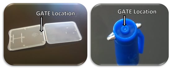
Injection molding relies on pumping molten plastic into a cavity that is the exact shape of the part you want (actually, the cavity is a little larger to allow for plastic shrinkage as it cools). For the memory card holder, the mold was very thin and long. The molten plastic was pumped into the cavity, likely in about a second, through a small port located where you see the little nub. Plastic flowed outward from the gate until it filled the entire cavity and formed the edges of the holder. The plastic was then allowed to solidify as the injection stopped and pressure was lowered.
The mold cavity opened up and the piece was pushed out of the mold; a small amount of residual plastic came out of the injection port (the gate) and stuck on the final part. As the pen cap and the card holder are very simple molds, there is not much else to see. These molds were almost certainly comprised of a simple “straight-pull” two-part mold: a top and a bottom cavity held together under very high force to resist the internal pressure from the injected plastic.
Increasing the Complexity
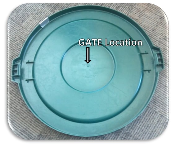
To get a better idea of more complicated molds, let’s look at a much larger piece. Below is the cover to a large recycling bin from our assembly room. Note that the nub on this part is much larger. This accommodates the larger volume of plastic that is used to fill the mold cavity. If the gate were too small, the back-pressure might be too high and it would be difficult to fill the entire cavity before the plastic began to cool. In the molding industry, an incomplete fill caused by such a problem is called a “short shot.” (It’s a nice alliteration but doesn’t sound as good when you start singing, “hit me with your short shot…fire awaaaaay”). In any case, I digress, you don’t want short shots and a mold manufacturer knows best to avoid these.
If you look closely at this lid part, you will see some additional complexity that you can’t see in the smaller parts. Look at the hooks near the handles and you will see a series of lines in the plastic. These lines tell us a lot about the mold that was used to create this part. Because of these hook/clasp features, a simple straight pull mold would not work. The clasps would simply hold onto the mold and it would never eject from the cavity. Mold-makers call these features “undercuts.” To keep molds cheap, we try to avoid undercuts. This can be done by adding a hole in the top of the cover, but this isn’t desirable if you’re storing smelly garbage.
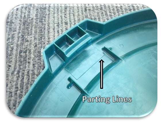
The mold for this lid employed several mechanical cams (a moving metal part that creates these undercut features) that pulled inward and away from the clasp as the mold opened to release the part. The small parting lines left in the plastic indicate where the cams had been located and moved during the molding process. Additional complexities like these cams can double the cost of small molds.
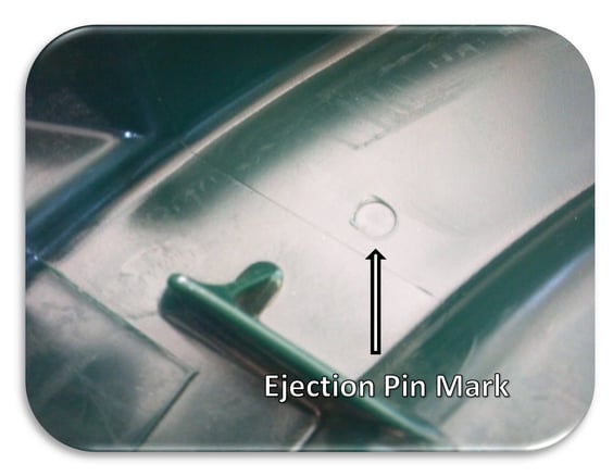
Looking more closely at the lid, it is apparent that there are small circles dotted across the inner surface. These circles indicate the locations of ejector pins. To quickly remove parts from the mold, small metal pins are pushed out of the core's surface and impact the plastic. The plastic part then falls into a large bin and the mold closes again, ready to form a new part.
Making a Simple Mold
To further clarify the process, let's pretend that we are making a small, red plastic bowl. It will be made out of polypropylene because it is a readily recyclable plastic and very affordable. Below is a picture of the small bowl, an extremely simple part. Because this part is to be molded, all the side walls must have a draft angle of at least 0.5 to 3 degrees. This will allow it to release from the mold. If the part were to have deep textures (a rough surface) the necessary draft angle increases to ensure that the plastic doesn't get stuck on the mold.
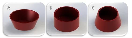
Injection Molding Bowls. (A) An easily molded polypropylene bowl. Note that the sides slope outward at a draft angle to allow easy release from the mold. (B) A difficult to mold bowl. The straight walls will inhibit release from the mold. (C) A nearly impossible part to mold without very expensive mold costs. Note that a simple two-part mold would get stuck inside the container and would never release without breaking the piece.
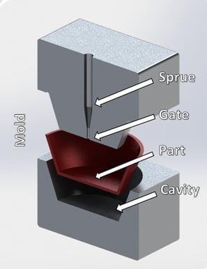
The mold for this simple part would look something like what is shown below. Note that this is an extremely simplified version. I have added a few labels for the important parts. With a part this simple and significant draft angles, ejector pins might not even be necessary. The draft angle refers to the slope of the side walls (the faces that are not perpendicular to the travel of the mold parts). For our bowl, the draft angle is about 23 degrees. We would not want to go any less than 0.5 degrees for smooth surface and not much less than 2-3 degrees for heavily textured surfaces. If you look back at the pen cap, note that all the near-vertical faces are actually very slightly angled. Even the small ribs in the memory card holder get thinner as they rise from the surface.
If you are interested in injection molding or have a rough part design that you would like to get ready for molding, the internet is full of great tutorials for design and the manufacturing process. Check out Protomold’s website for some great tutorials, including one on designing and molding living hinges.
As always, you can learn a lot from the products and designs you see everyday. Take a look around and some plastic parts can give you great clues as to what their mold looks like and how it functions. The little nub we explored earlier can even tell you about how big the mold’s gate is!