.svg "bes-logo (1)")
We recently worked on this vibration-absorbing washer as part of a larger design requiring a sheet metal enclosure to be isolated from its machine frame. Because we expected the rest of the assembly to rattle frequently, we made this simple washer out of a soft neoprene rubber (50A durometer—similar feel to a pencil eraser) to take up some of that vibration. Here’s the initial model of the part:
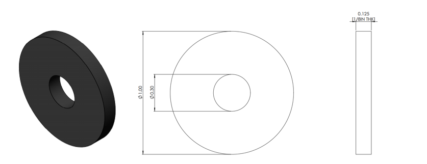
Figure 1. Initial washer design and chosen material (rubber) thickness.
We initially planned for these parts to be laser-cut for the first prototype. However, as we started scaling up in production and were looking at quoting 1500+ washers at a time, it became clear that we’d want to pivot away from a CNC method and into a manufacturing method that would sustain larger quantities. Laser-cutting is very cheap and requires no tooling, but it is much slower than other production methods, since parts must be cut one at a time by the moving laser head. Because these parts are relatively simple, they seemed like logical candidates for a die cut manufacturing approach.
For those unfamiliar, die cutting is great for high quantities of 2D parts. It operates similarly to a cookie cutter, but for non-cookie materials such as rubbers, metals, and plastics. Once a satisfactory die (the cutting tool) is made, it’s easy to fabricate a large number of identical parts very cheaply. Die-cut tools for rubber are generally low-wear and as such relatively inexpensive for medium to large quantities.
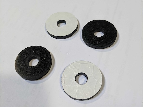
Pretty quickly, however, we got some interesting feedback from our die cut fabricator: there was a wide variation in the part geometries, specifically the washer’s inner diameter (ID). Here are some of the samples we received below, roughly grouped in ascending ID size.
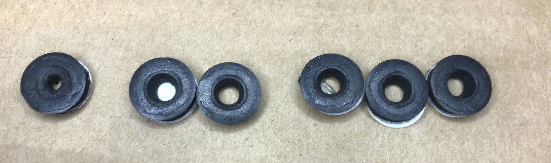
Figure 2. First article die-cut samples. Note varying internal diameter size.
In some cases, especially when we want to meet tight deadlines, we can roll with manufacturing defects for prototyping if they don’t greatly affect the rest of the assembly or can be modified on the fly—prototyping is the phase for making mistakes that we want to iron out in production, after all. Here, the ID of the washer is the only critical dimension on the part, so unfortunately this was not one of those cases.
What’s going wrong?
So what’s happening here, and how do we fix it? Talking with our vendor, we determined that there were likely two culprits: first, the low-durometer (IE soft) material; and second, the geometry of the part.
When the die is pressed into the material, the rubber is flexible and starts to bend out of the way. This compression is also why we see the extreme tapers on the hole IDs (the ID is much narrower on one side of the material compared to the other). With our part geometry as designed, the walls of the washer were about as large as the washer was thick, meaning that when the inner wall started to deflect, there wasn’t much material to resist that deflection. These two factors combined to cause parts with varying IDs, most of which were trending small.
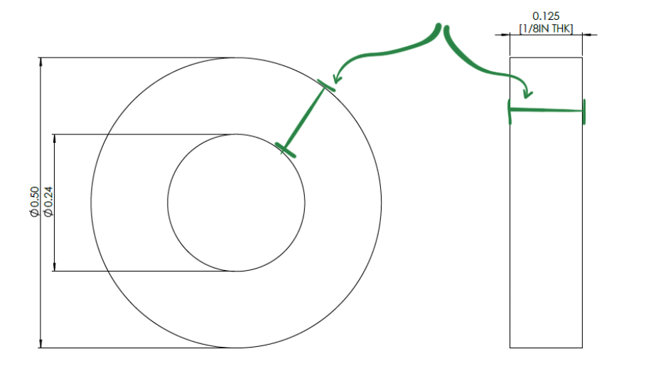
Figure 3. Washer width is about equivalent to its thickness—this can cause issues while die cutting.
Possible Solutions
Right, so mystery solved. Now what? Working with our vendor, we were able to compare several possible solutions:
- Work with what we have—some of the holes are bigger than others, so we could proceed with this die and scrap the rejects
- Change the part geometry—decrease the part thickness by approximately half
- Change the part geometry—increase the part outer diameter (OD)
- Change the manufacturing method—use a digital cutter, go back to laser cutting, etc
Looking at these options: (1) is not ideal and wasteful, especially if the reject percentage is high. (2) has potential and would fix our problem quickly, but the assembly was designed for slight compression on 1/8” material. Without changing the other parts, halving the thickness would mean assembling twice as many washers—not terrible on a small scale, but when we’re going from assembling 1500 washers to 3000, the extra assembly labor time and cost adds up. (3) seemed quite possible for our application, especially since the exact dimensions of the OD aren’t critical to the system design. (4), while useful as a last resort, offered no advantages if we could simply adjust the design via (3).
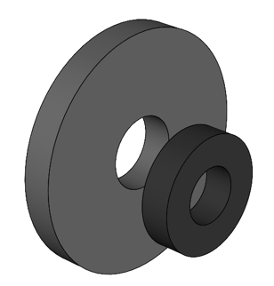
In this case, the washers were internal to the design, so they weren’t interfering with other parts and they weren’t visible from the outside, which meant we could bump up the OD to nearly double its original value without affecting the rest of the assembly. This was a straightforward change on the design end that made successful manufacture much easier.
And, behold! The subsequent samples from this revised design were much more uniform:
|
|
Figure 4. [Left] New washer design compared to the original. [Right] First die-cut articles with improved consistency of ID and OD dimensions.
Lessons Learned
Although part of our washer issue was rooted in the gory details of a niche field like die-cutting thick, semi-rigid materials, this problem demonstrates a common theme when adapting parts from small-scale fabrication to a larger-volume manufacturing method. In this case, as with most phases of design, it was critical that we were able to communicate quickly with our manufacturer to understand which changes would be made design-side to facilitate successful fabrication at scale.
We often see similar design changes needed in the Design for Manufacture (DFM) stage, where part geometries, assembly methods, and materials tend to get design tweaks to facilitate volume manufacturing methods that wouldn’t be useful in prototyping or would involve high capital expenditures for NRE (Non-Recurring Engineering, IE high-volume die cut tools). BES has a lot of experience with this sort of hands-on DFM and working directly with manufacturers to not only best suit their methods with our designs, but also to best fit their facility. By making parts better suited to a specific manufacturing method and manufacturer, we can often make product more cheaply and with less waste!
-----------------------
For considerations we make when moving plastic parts from 3D-printed prototypes to large-scale injection molded products, check out the below blog posts.