.svg "bes-logo (1)")
Materials
Strengthening Electronic Manufacturing with FCT Fixtures. A Functional Circuit Test (FCT) fixture is a critical part of ...
Strengthening Electronic Manufacturing with FCT Fixtures.
A Functional Circuit Test (FCT) fixture is a critical part of quality control in an electronics manufacturing environment. FCT fixtures evaluate a board in a powered on and in application capacity. In order to achieve this, circuitry is designed into these fixtures that replicates the end application so that the subsystems can perform the necessary functions and confirm that they are operating as they should. FCT fixtures can also serve development and debugging purposes. They reduce cost and aid in hardware and firmware development of a PCBA during early, middle, and late stages of development. Prototyping, software development, and final production of a circuit board can all benefit from an FCT fixture. This is true even for medium scale production of PCBAs. Early development of an FCT alongside the PCBA allows for better visibility of each subsystem during prototyping. For more information about how BES integrates software and hardware development, see Hardware vs. Software Development.
Integrating PCBA prototype design with an FCT benefits from early prioritization of Design for Test (DFT). A common type of FCT that BES uses is a bed of nails design, typically consisting of pogo pins that interact with test points on the PCBA. There are inherent advantages to working this way from the beginning. Other methods of interacting directly with components and subsystems, such as putting tiny air wires on development boards, can cause damage to expensive early designs and often require a highly skilled technician who may not always be available, even to a business that has the resources. Rather than putting valuable time into pulling out air wires during development, a pin board can be employed over and over again for many different purposes throughout development, with no detriment to the prototype PCBAs.
At BES, we prefer to get our hands on a bed of nails FCT early in the process with as many test points on critical subsystems as possible. We have polished our FCT fixture design over the years and have found a few things that really work for us. We pair custom pogo pin boards with separate control boards. This allows for changes in each separate board without needing to reprint changes on the other. The same pogo pin board can be reused throughout the prototyping process, or vice versa. As electrical design continues to trend toward miniaturization, bed of nails alignment can be a challenge for these types of boards, making early prioritization of test point placement useful and worthwhile.
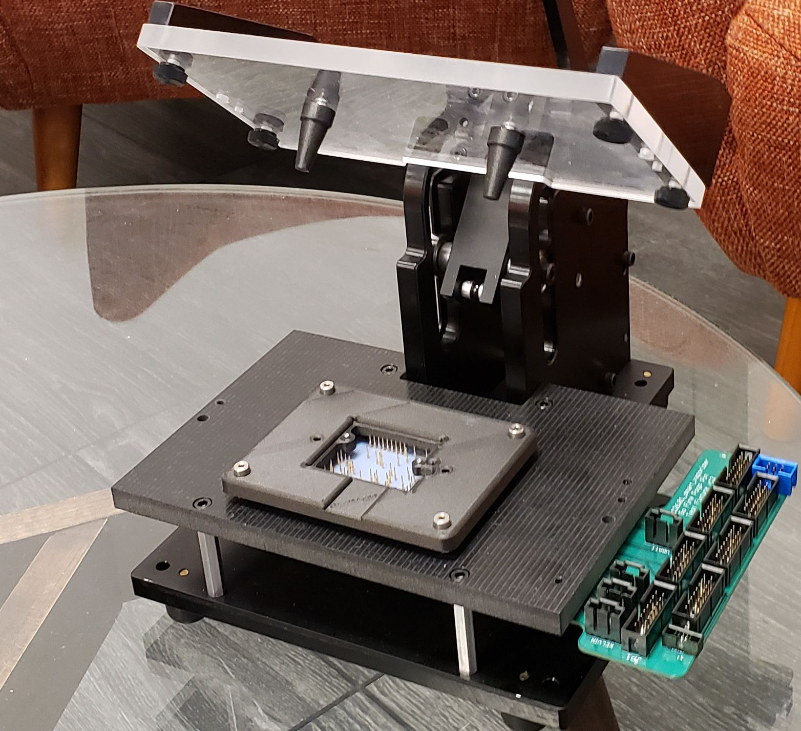
In many cases, pogo pin boards are made out of perf boards when it is possible to arrange them at a standardized pin pitch, but with a high density PCBA, keeping up with that alignment while getting enough visibility on important components and systems can be an insurmountable and indeed unnecessary challenge. A custom board to carry the pogo pins therefore becomes necessary and highly preferred. At BES, we employ a guide plate drilled to be press fit or near press fit for the pins to help with alignment, especially with high density boards. The pin sleeves rest on the guide plate, while the circuit board is fitted on the other side of it. We have found that this allows for larger holes in the pogo pin board, which in turn allows for a better solder fill in the through holes. Because signal integrity is very important with an FCT, there is much advantage to this method.
At BES, we employ few methods to help us align our pin boards with the DUT. One of the most useful ways to visually see alignment is by covering test points with a thin layer of tape. When the taped board is pressed in the fixture, we are able to see indentations in the tape where the pogo pins are making contact with the test points. This allows us to easily pinpoint locations where a sleeve can be gently bent to align it better. We also can include headers on the FCT control board with breakouts that allow us to measure the connections with the DUT while it is pressed in the fixture.
There are several ways to integrate pinboard design with a particular PCBA. In the case of a flat board, a bottom up design is preferred. It’s really about saving as much time as possible during testing while getting the best possible alignment. We prefer to use a ready-made press fixture to house our bottom-up design. They are made to provide even pressure, and therefore help us ensure that we are making proper contact with all pins on the DUT (device under test).
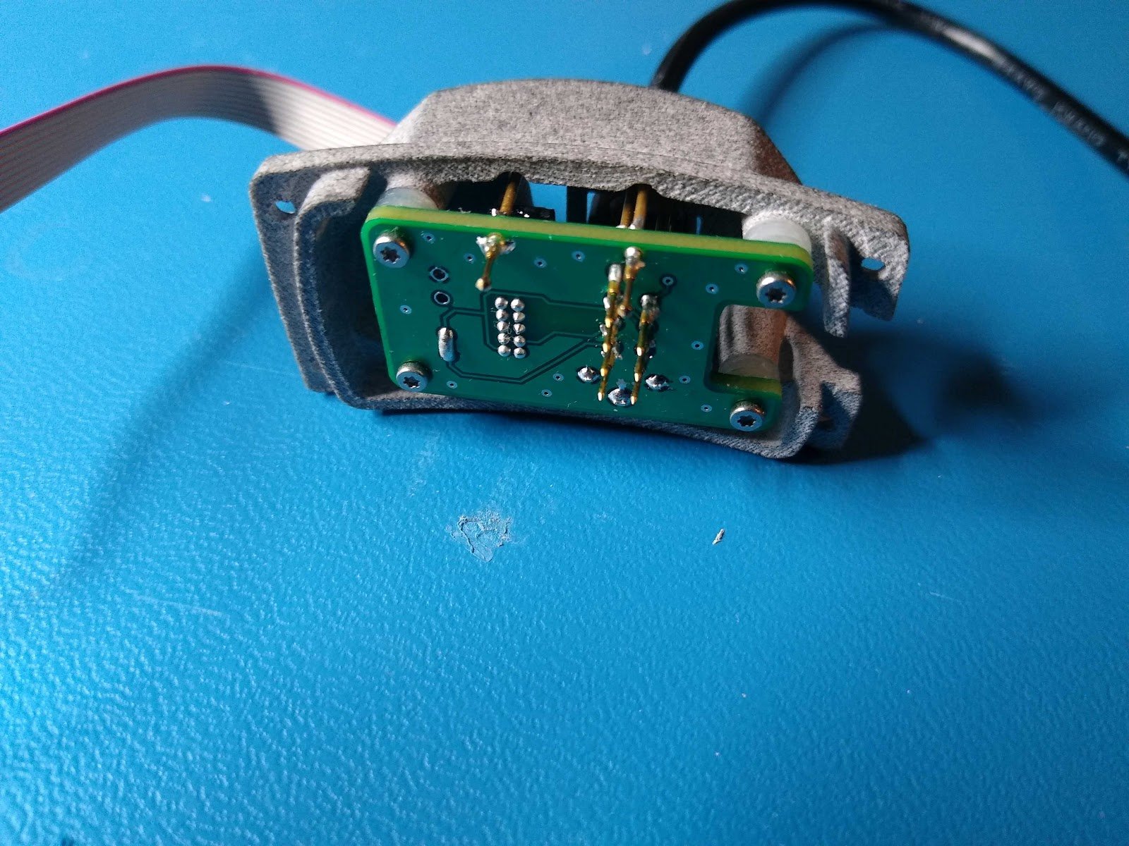
There are other cases in which a bottom up design may be better, for example with an already enclosed or over molded PCBA that needs a custom fit pin board. In this case, we find that a smaller, hand held bed of nails works better and is easier to use by an assembly technician or test engineer. Sometimes, a little manual variation of the alignment is needed with these already integrated designs. Ease of use is key here, and our designs change to accommodate each individual system. This is a particular advantage to our method of producing the FCT control boards separately from the pogo pin board. We can have more flexibility in how the pin board interacts with the DUT without needing to fully redesign each part of the FCT.
For a complex consumer PCBA design, development of an FCT well before the design goes to manufacture can help the team create a strong system before it becomes much more costly and urgent. For example, when the board design is handed over to a large scale contract manufacturer, having developed iterations of the test fixture along with the PCBA has already led to a more polished design long before it is needed on the factory floor. More information about Design for Manufacture (DFM) can be found in Design for Manufacture: Electronics. There are strong advantages to integrating an FCT fixture in contract manufacture’s quality control processes, and it typically serves the development team greatly as well.