.svg "bes-logo (1)")
Machining
3D printing turns forty next year, which is young as far as fabrication processes go. The earliest sawmill is about eighteen hundred years old, while the earliest forged iron tools are at least four thousand. As a result, we find that the capabilities of 3D printing are still evolving alongside the application—people are answering “what can we print?” at almost the same time they’re answering, “what can we print this for?"
You may have seen our previous partnership blog with Protocase, where we explored how 3D printing can be used to create sheet metal parts that might not otherwise be formable at a prototype level. In this blog, we’ll go through some of the ways that we integrate both 3D printing and sheet metal fabrication to create higher-performing prototypes that combine the strengths or mitigate the weaknesses of either approach in isolation.
Playing to Your Strengths
At BES, we prototype often—it’s the most effective way to stress-test a design. Quick-turn manufacturers like Protocase are invaluable for keeping our timelines intact while we prototype, but sometimes it can be tricky to make a prototype that behaves like a manufactured part. That’s where combining different prototype fabrication methods comes into play, since we can use the strengths of one method to cover the weaknesses of another, and vice versa. Having access to a variety of fabrication methods under one roof is useful if you’re trying to get a prototype built on a fast, inexpensive turnaround that works on the first try.
Often when we are working on a new product for a client, they have some specific needs which lend themselves well to combining 3D printing and sheet metal prototyping approaches. For instance, a prototype might need a variety of easily testable configurations without having to spend lots of money or time making all the different parts. Or possibly, the product could have any of several appearances and physical configurations which could be evaluated by potential users, using parts that resemble production parts but without investments in tooling or machining time. There may be a desire to field test several different attachments or a mixture of plastic and sheet metal components easily. A customizable set of material properties may easily be obtained by clever combination of simple sheet metal and 3d-printed parts.
To understand how to successfully combine sheet metal and 3D printing, we need to understand the strengths and weaknesses of both fabrication methods. Sheet metal is durable; has good heat, chemical, & corrosivity resistance; and is less expensive for covering large amounts of shape, such as brackets and enclosures. However, sheet metal is geometrically limited to shapes that can be bent, heavy, and generally takes longer to fabricate on the prototype-level.
Comparatively, 3D prints can be made with lead times as short as a day, are very geometrically diverse, and require no tooling costs or setup-times. On the other hand, 3D prints are not as durable as injection molded or machined parts, aren’t held to precise machining tolerances, and are expensive at manufacturing-quantities compared to other manufacturing methods.
Below, we’ll look at some applications for combining these processes effectively.
Rapid Design Iterations
For this prototype, we are testing the dynamic range of a trio of LIDAR sensors in poor weather conditions and determining the range of distances at which the sensors accurately locate a target. Because this prototype will be housing electronics outside and exposed to rain, we want to make sure the enclosure is durable and waterproof. In order to support a long runtime, the enclosure will need to house a fairly large battery.
Stationary LIDAR best targets objects in a straight line ahead of the sensor, so the simplest way to change where the sensors focus is to change the mounting angle. A wider angle between LIDAR beams results in a closer focal length. An example of two different sensor layouts is shown below. Note that the focal length here is dramatically reduced so that the image fits on the screen; the true focal distances range between 1 and 20 feet.
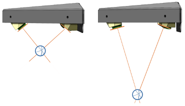
The first half of these project requirements are suited to 3D printing. Printing has a fast turnaround time, so we can make several versions where the sensors mount at different angles to vary where the sensor trio’s lines of sight intersect. The second half of these project requirements are suited to sheet metal—formed metal is great for durable and impermeable enclosures that need to enclose a lot of volume.
For testing purposes, we’re iterating through multiple sensor positions but only expect to use one of them in a final design. The data from this prototype would guide a production design with a single sensor position, at which point it would make sense to invest in tooling for that specific part. However, when we’re quickly testing multiple configurations of a device that still needs to be durable, it makes sense to mix manufacture types here. We’ll keep the housing (grey) in sheet metal, but we’ll print through several iterations of the sensor mount (black).
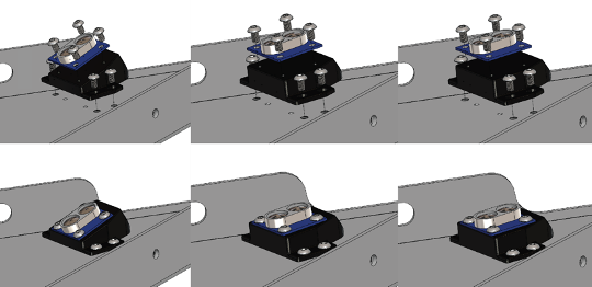
The angle difference between the lengths we actually want to test is visually negligible. For a 12-foot focal distance, we angle the sensor back 91.65 degrees; for 15 feet, we angle the sensor 91.32 degrees. As a result, for visualization purposes we also printed some “dummy” versions that have a more exaggerated difference in their tilt angles to better show the versatility in the 3D printed mounts:
These parts would be tricky to form in sheet metal, especially for bend angles that require tolerancing to a tenth of a degree or tighter—these parts would have a long lead time and might not come to spec. But for 3D printing, this is a cinch, and we can easily cycle through iterations with tiny incremental differences during our test phase.
Aesthetic Control
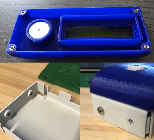
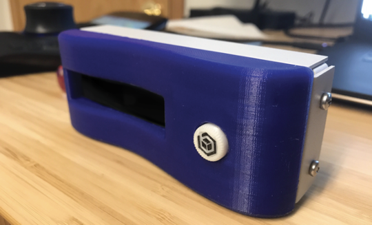
This project has a user-facing component consisting of an adjustment knob and an LCD readout screen. As far as housing design is concerned, this is a fairly straightforward project and we get a lot of free reign from a design perspective. We were asked to match the more organic, wavy look in other members of the product family if possible.
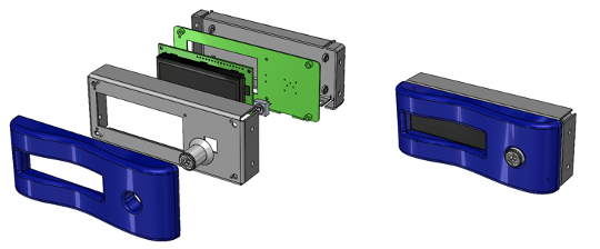
In this case, 3D printing the housing is tempting, as it would allow us to make the external shape something a little more visually interesting than a box. We would also benefit from faster lead times and lower costs. However, for structural integrity and heat dissipation, a metallic enclosure would be a more mechanically-sound option, but we would struggle to get organic curves on a prototype budget. Once again, using a mix of both metal and plastic lets us get the best of both worlds—because of how this part is recessed in a larger assembly, we can use sheet metal for the structural components of the housing, and then print a façade for the user-facing side.
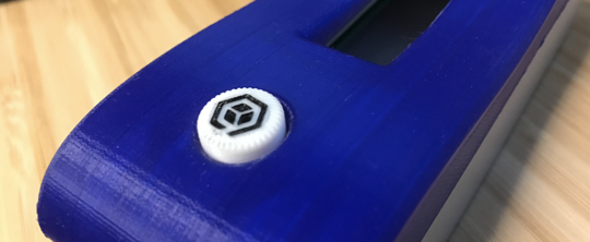
We can also mix and match for the knobs on the front. In prototypes, components such as knobs, dials, and switch covers can be hard to source in small quantities, so we often find we’ll print one or two before we commit to ordering a hundred. This also gives us a little more control over the user-interface components, such as the debossed logo on this custom knob piece:
Beyond the industrial design applications of 3D printing, we often find ourselves using it in our mechanical tests as well. Another trick we can use here is printing a mockup version of the PCB—this lets us do fitchecks to make sure that none of the components will interfere with one another or the housing, but doesn’t force the electrical team to have finalized, production-ready boards this early in the design process. It’s worth noting that PCBA component placement tolerances are usually looser than 3D print tolerancing, so it’s helpful to oversize any component mockups to account for this. For example, the overlapping flanges that support the cable connectors here:
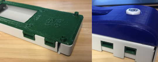
For fast assembly, we can once again take advantage of some of the unique strengths of sheet metal and 3D printing. With the printed facade, we can easily design a few holes for press-fit brass inserts, which will give us a much stronger connection than threading the plastic. For the sheet metal components, we rely on Protocase’s press-fit PEM studs, which give us ample thread length even with a thinner, lighter enclosure.
The resulting assembly is one that lets us test several different areas in one pass. Although this is a prototype setting, using sheet metal structure with plastic externals is common in manufacturing, albeit usually with injection molded parts instead of 3D printed ones. For an extreme example, an automobile is comprised of a metal chassis to handle shock loads and vibration (making these parts out of plastic would result in immediate mechanical failure), but uses plastic paneling to create organic internal surfaces. On a smaller scale, parts such as knobs tend to have a plastic exterior with sheet metal structural interiors.
Low-Weight, High-Wear
In this project, we’re designing a small, wearable device that has a few internal sensors for recording user activity data, as well as a Bluetooth/wireless transmitter to transfer that data and some other onboard electronics.
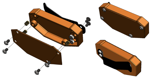
In the case of wearables, plastics tend to be the preferred material housing choice over metals: plastic housings are lightweight, skin compatible, and also tend to feel closer to body temperature when worn. Plastic’s less-desirable material properties tend to be less of a pressing factor in devices worn by humans—during typical use, wearables aren’t (or shouldn’t be) exposed to extreme impact or temperature.
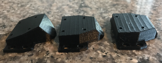
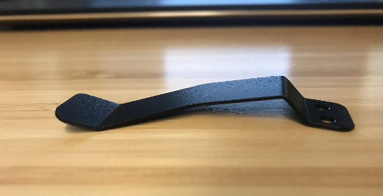
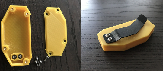
However, some components of this device would still benefit from the structural integrity that metal provides. Most pressing is the clip that allows the user to attach the device to their waistband: this part needs to flex slightly out of, and then back into, shape to clip on and off. It’s possible to design plastic parts that are capable of repeated deformation in this fashion, but a 3D-printed plastic part would need to be substantially larger and thicker than a metal part in order to have the same strength and would likely still break after enough uses. As a result, we get to flip the script a little, and 3D print a housing that supports an external sheet metal feature.
For the clip attachment, we used recessed nuts to create the threads instead of the press-fit inserts, which we used for the external assembly. The hexagonal shape of the nuts gives us more resistance to vibration and ensures that the movement from flexing/unflexing the sheet metal clip will not loosen our threads over time.
Blending In
Mixing manufacture methods isn’t uncommon outside of the prototype setting either. In this project, we need to interface between a camera and a larger lens stack on a telescope. Rather than redesign the entire camera, we instead want to design a part that will attach to the camera on one end and the custom lens stack on the other—in essence, we want to copy a lens mount.
Looking at the end of a compatible lens, we can see there’s a mix of injection molded, machined, and stamped parts here. The two parts we’re focused on in this prototype are labelled below:
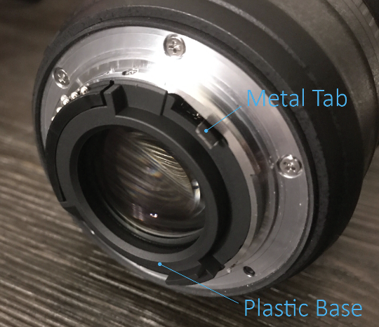
In some lenses, the base is made of machined metal as well. For a very fast fitcheck, we’d be okay 3D printing this part—to interface with a camera, we’d ideally want a smooth, machined surface with tightly-controlled tolerances, but we often do quick prints in order to sanity check our geometry before making the plunge to machining. The protruding metal tab is also important, as it interfaces with a spring and allows the lens to click into place. However, we definitely wouldn’t want to print this part, even for a fit-check—it’s a bit thin for 3D printing standards, and we don’t want to risk snapping it off inside the assembly and jamming/scratching the camera.
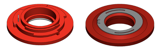
In this case, we mix methods for these two prototypes so that we can interface with existing designs. We print the base, and we bend the tab out of sheet metal. In this case, we keep the sheet metal tab relatively simple and only focus on making the part that will interface directly with the camera.
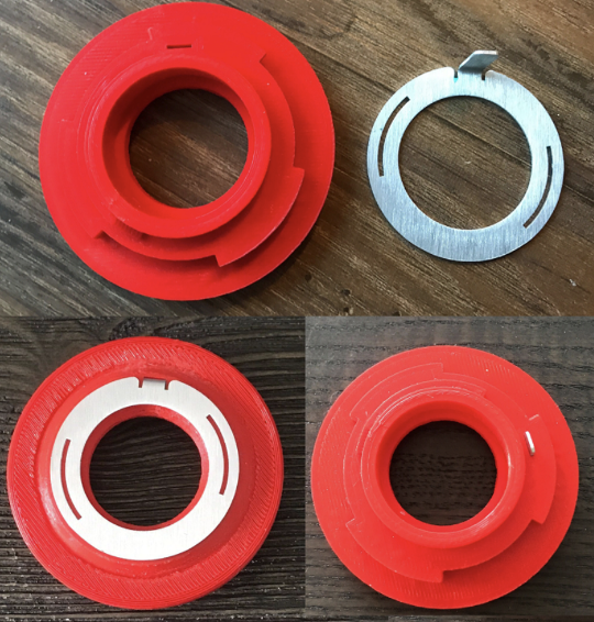
Assembly on this one is the simplest so far—the sheet metal tab slots into the 3D printed piece, and then we fitcheck on the existing assembly:

Wrapping Up
To summarize, these are just a few of the areas where we can combine sheet metal and 3D printing to get more than the sum of our parts:
- Test stands and brackets that need fast iterations
- Rapid iteration of complex parts with strong mounts
- Sturdy, eye-catching enclosures
- Custom electronic user components such as knobs/switches
- Test fits stand-ins for more complex components such as PCB’s
- Functional clips and attachable 3D prints
- Adapting to existing mixed-material parts
Even with four projects in different fields, we’re really barely just scratched the surface as far as application goes, but hopefully we’ve given you some jumping off points for how you can combine these two methods in your own designs!