.svg "bes-logo (1)")
Mechanical Engineering
Machinists Hate These Six Simple Tricks
Machinists Hate These Six Simple Tricks
Machinists’ toolboxes have expanded massively in the past decade. Widespread access to methods such as EDM, waterjetting, and five-axis machining means that even tiny shops can consistently produce high-quality, complex parts that wouldn’t have been feasible ten years ago. As an engineer looking to capitalize on all the new tools at your disposal, it might be tempting to design quickly and let your machinist figure out the rest.
But, as with everything—just because you can doesn’t mean you should.
Machining prices are generally based on machine time and material cost, so large, complex parts made of fancy materials will cost more. Because of the myriad of new techniques available, some parts become technically possible, but realistically difficult. There are less obvious ways than size and material that complexity can sneak into your design. We’ve highlighted a few common ways to work difficult machining out of your design—and in turn to keep your machinists happy and your part cost down.
Excessive Material Removal
Machining is a subtractive process—you start with a stock part that is larger than your final part, and you remove the excess material. Compare this with an additive process such as 3D printing, where your build area begins empty and you add material to create a part. For additive processes, your material cost is governed by the volume of the finished part. For subtractive processes, your material cost depends on the volume of the starting material.
Compare these two versions of the same part. The top version shows the original part, as well as how much starting material we would need to machine it. In addition to being costly due the larger material envelope, the tall and unsupported portions would vibrate during machining, meaning a machinist would need to be much more careful to ensure tolerance adherence and a good surface finish.
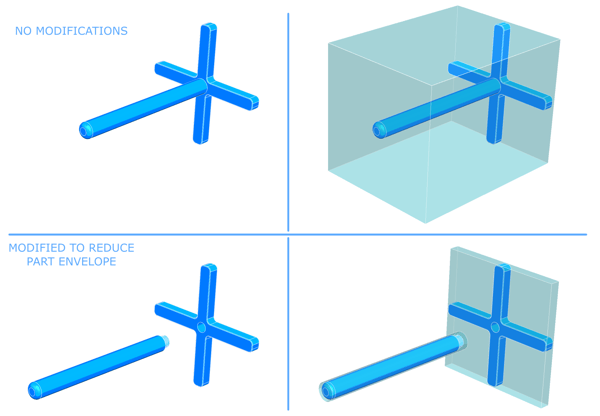
The bottom version splits the design into two parts that can be machined separately and assembled. The resulting material envelopes are much smaller, and it is much easier to control quality without the unsupported sections.
Tolerance Overkill
Fire up your first CAD drawing, and you might find that your output looks a little like this:
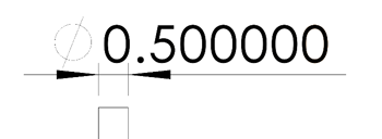
Bear in mind that in the world of machining, a looser tolerance usually means being incorrect by less than a few hundredths of an inch—for most dimensions, this isn’t even noticeable. However, a good machinist will match all tolerances as they are called out, whether they think it’s critical to your design or not, so the burden is on you to only call out the tolerances you need.
Internal Sharp Corners
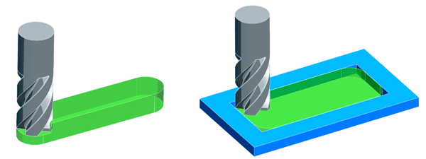
This pair of parts interlocks in an assembly to form a sealing surface, with irrelevant parts removed for visual clarity.
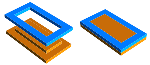
In milling, material is removed via a rotating blade called an endmill. Using an endmill to remove the inner corners in the part above would mean trying to fit a round tool into a square hole—we can reduce the radius of our internal corner by using smaller and smaller endmills, but to get the 90 degree corner shown in the original part, we would have to use other techniques beyond the mill, which would drive up cost.
The cutting area (shown in green) of a sample endmill in an internal corner
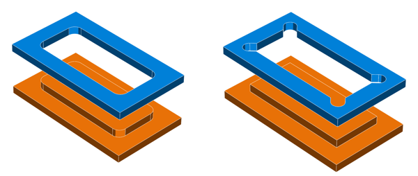
Consider two minor changes to part design instead: filleting internal corners and their corresponding mating features, shown left; or, adding relief cuts for the endmill, shown right.
Too Many Threads
As with tolerancing, it’s tempting to go for overkill when calling out tapped holes. Remember that tapping is an additional process that must be performed after machining is complete: tapping more threads means more time, so higher cost. As a general rule of thumb, you should aim to keep your ratio of [hole diameter]:[thread depth] at around 1:1.5. For lower load applications, you can get away with even less thread engagement.
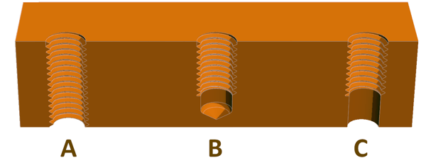
In the image above, (A) has twice as many threads as you realistically need, while (B) and (C) have much fewer threads but offer almost identical strength. (B) shows an example of a tapped hole with a clearance hole drilled to ease the tapping process while still allowing for a smooth surface on the opposite side; (C) has a through hole to allow for tap and screw clearances.
Deep Pockets
If we look at the endmill, we can see that only a portion of it can perform cutting:
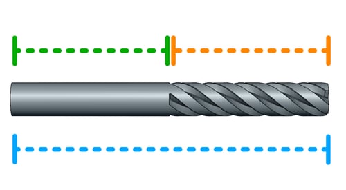
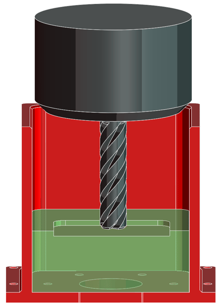
The cutting length (marked orange) has sharp blades, called flutes, which are designed to cut away material while the tool is rotating. The shank (marked green) is rounded to let the tool fit in the mill, and also provides torsional stiffness. The total length of the tool (marked blue) is usually noted, but for design purposes it’s important to make sure that we only use the cutting length to remove the material. Cutting with the shank in contact with material creates a risk of catching the shank on the part. Additionally, cantilevering the endmill during cutting causes the tool to deflect and vibrate, which results in a poor surface finish and lost tolerances. The final issue with cutting pockets deeper than the cut length is perhaps the easiest to visualize: the tool simply will not fit in the pocket:
Unnecessary Machine Setups
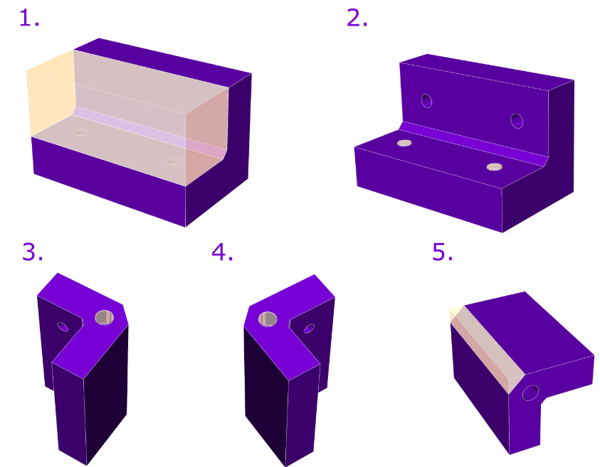
In traditional machining, the part is clamped to the workstation, and material is removed by a tool that has movement in an X, Y, and Z-axis. You can think about this by looking at the part from one direction—you can only remove material that you can see. Compare the two views of the same part below.
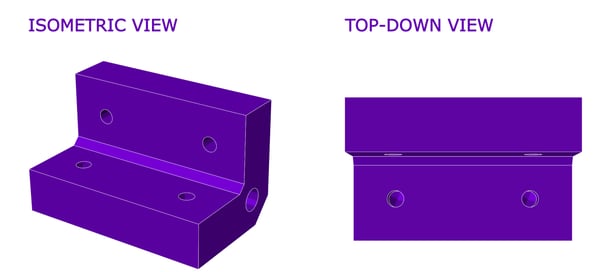
If we want to remove material from a different side of the part, we will need to unclamp the part, change its orientation, clamp it again, and then recalibrate the machine for the new setup. This process is called a machine setup. More machine setups means more machine time, which means more cost. The simple-looking part above actually requires five machine setups.
Material Selection
Comprehensive material selection for machine design could be a textbook of its own, but we will briefly touch on it here. Harder metals such as aluminum and low carbon steels are favored by machinists for their low deformability and high machinability, which translates to more precise parts.
Some materials should be avoided unless the design specifically calls for it. Softer metals such as copper will gum up tools very quickly. Stainless steel and titanium exhibit a property known as work hardening—when machined, they will change on a molecular level and become harder. While useful in parts, this property is undesirable in machining, as a change in tools or machine setups could give the part enough time to harden, which will result in difficulties. These material characteristics are known, and a good machinist will be able to work around them, but you will typically see an increased price.
Takeaways
In general, the recommendations above are simply best practices. In many cases, your design specifications may be such that there you absolutely need to design a certain geometry, setup or material, in which case you’ll want to focus on finding a good machine shop that can help you manufacture complex parts with ease. It may also be possible that some of the part features discussed above have slipped into your design by accident, and working around them can greatly reduce your parts cost. Each project is unique, and ultimately you’ll have to weigh the pros and cons of when to change your design to suit machining, and when to use more complicated machining to suit your design.