
Programming and test fixtures
eLink™ fixtures, from engineering bench to production line
A flip-top fixture platform for programming and testing PCBAs and finished devices, used in aerospace, medical, undersea, automotive, industrial, and manufacturing programs. No per-seat programming license fees.
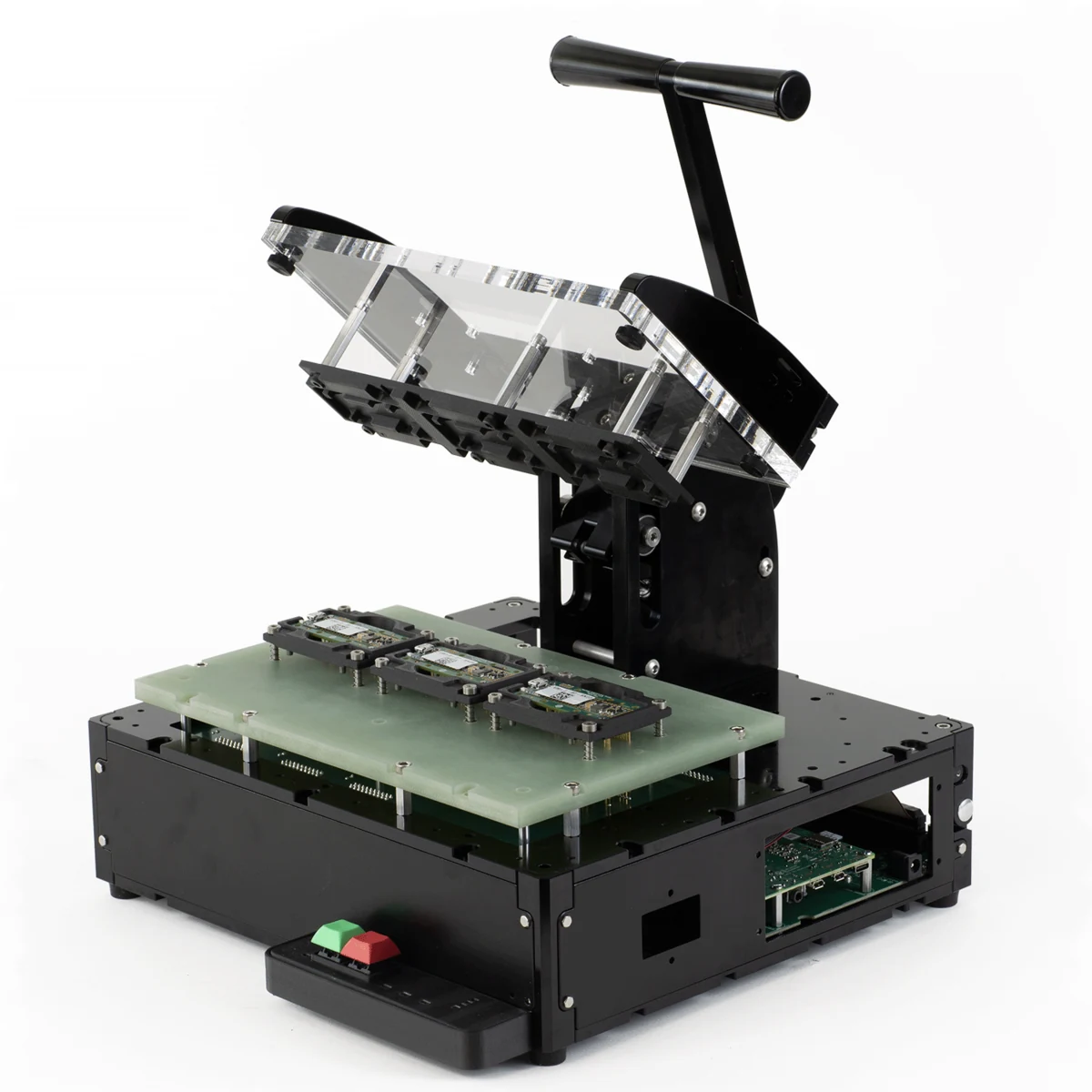
Access
Spring-pin access to your test points, from the first prototype board onward, replaces fly wires and the debugging time they cost.
Detect failures
Program and test each unit the same way, with bench instruments or custom test hardware, and catch failing boards before they ship.
Report
Each result is logged and can be sent to your systems. Fixtures take software and configuration updates remotely, so all stations run the same test whether or not you are on the floor.
Who it is for
Measure the real board
Reliable pin access to as-built hardware replaces the rat's nest of fly wires. Measure actual performance instead of relying on simulation.
Run each unit the same way
Program and test one unit at a time, several in parallel, or a full panel, by changing configuration rather than hardware. Results export to your systems or your customer's, with no per-seat license cost at each station.
Debug on real hardware
Reach any module on the as-built design instead of a cobbled-together development kit, and triage real issues as they happen.
A record for each unit
Track passes, log failures with their measured values, and quarantine failing units. The same record follows the product through NPI, production, and returns.
What makes an eLink fixture
eLink is sold as three parts: Frame 01 Gen 2 (BT201), the flip-top press; the eLink Test Runner SDK, a software development framework and operator GUI; and configuration and customization services that adapt both to your product. Buy the base frame and build on it yourself, have us integrate hardware you already have, or have us design the whole fixture.
Inside the frame, a fixture has three working elements: the DUT interface, the control board, and the test runner. The base frame ships without requiring customization. DUT interface and pogo design, control board design, and software and GUI customization are added as a design package, sized to what your product needs.
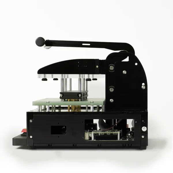
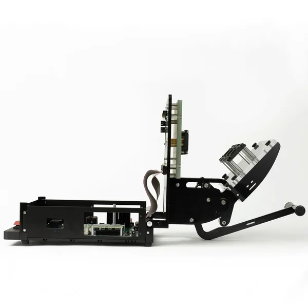
Frame 01 Gen 2 (BT201)The flip-top press. Sold on its own as the base frame.
eLink Test Runner SDKA software development framework and operator GUI.
Configuration and customization servicesDesign package: DUT interface and pogo design, control board design, software and GUI customization.
- DUT and test requirements
- Test runner architecture and hardware development
- Fabrication and test
- Validation and commissioning
- Deployment
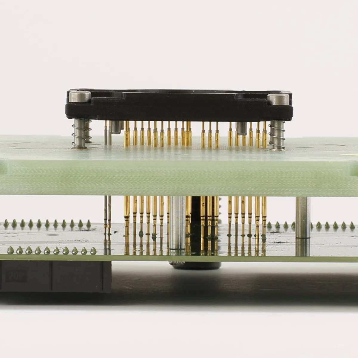
DUT interface
Reach all the test points on your DUT.
How we build it
Pogo plate assemblies give repeatable contact with dense test points. Machined nests hold the DUT in place during test and release it quickly before and after. The pogo plate mounts on a 50 mm grid with 46 threaded positions, inside a DUT area of 230 × 140 × 35 mm.
What to expect
- Direct-soldered pins.No wire-wrap and no crimped connections, and ribbon cables in place of loose signal wires.
- Fast to deploy.Custom fixtures in as few as 4–8 weeks.
- Open underneath.The hinged chassis opens without tools for board debug and component swaps.
- Modular.Spring pins and nests are replaceable, so a worn part is a short repair rather than a new fixture.
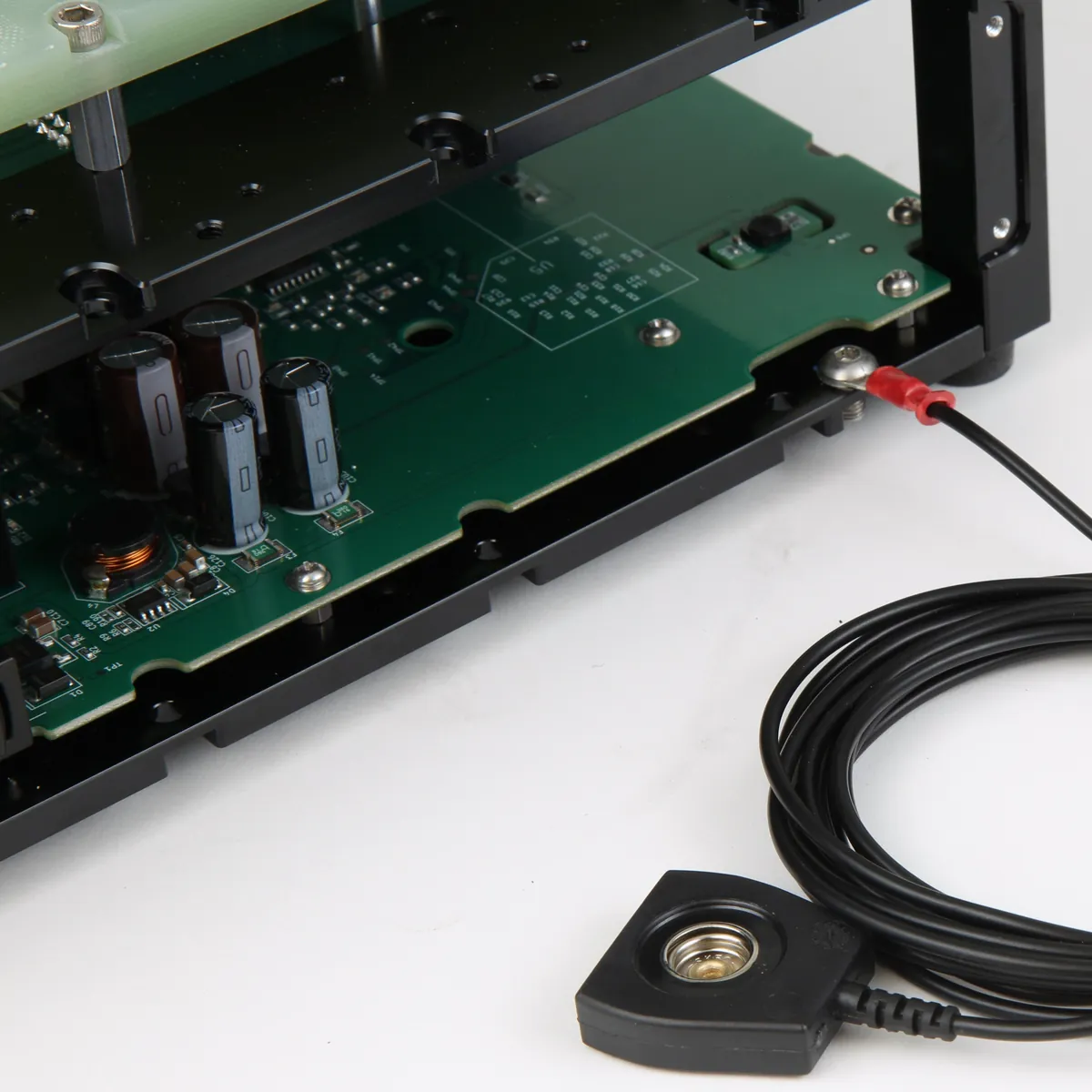
Control interface
Power, test, and communicate with your DUT.
How we build it
A control board, designed for your product as part of the design package, powers the DUT, talks to it, and runs the measurements. It also connects the peripherals your line uses, such as screens, programmers, and barcode scanners. Short cable and trace runs between the board and the DUT keep signals clean.
What to expect
- Built for your test.Proven design blocks are combined into a board for your DUT.
- Fewer cables.Onboard circuitry shortens cable runs and reduces programming errors.
- Documented.Each board is drawn from our layout library and delivered with documentation.
- Easy to connect.Configurable headers make setup and access quick.
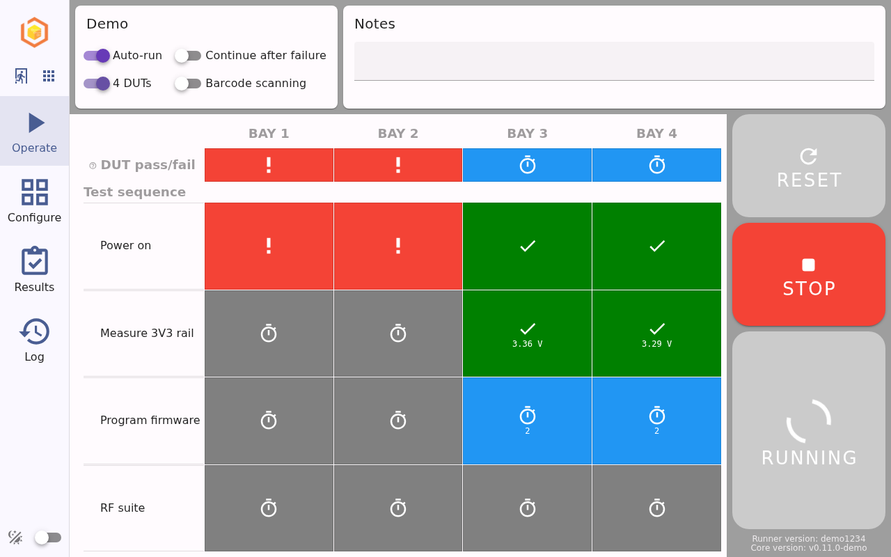
Test runner
Pass good units. Catch the failures.
How we build it
The eLink test runner SDK is a software development framework designed to enable rapid deployment of test fixtures. Your test sequence is a list of procedures, run in parallel across all DUT bays in the fixture, and each procedure returns a pass or fail with the measured values stored alongside it. Signal switching lets several DUTs share measurement circuitry, which holds down hardware cost while keeping tests parallel. The operator GUI walks operators through each cycle.
What to expect
- Traceable.Results are stored on the fixture and can be exported through a web interface, an API, a USB drive, or to your cloud or on-premises systems.
- Containerized.Fixture software runs in containers, so one update package goes to one fixture or a whole fleet.
- Configurable.Limits and settings sit apart from the test sequence, so one fixture can test several board variants, and a technician can change limits without touching the tests.
- Simple to operate.Operators need no test background to start a cycle and read the result.
Demo
Watch a test cycle run
The eLink operator GUI, running against simulated hardware. An operator starts a cycle on four bays, one unit fails at power-on, and the result record shows the measured values for each unit.
Frequently asked questions
No questions match. Ask us directly.
What DUT features can be tested?
The list below gives examples, not a complete list. Power, measurement, and programming are part of most fixtures. Most of the items below need instruments or custom hardware added in the design package, and RF protocol testing is always design-package work. Ask us about anything not listed.
Physical elements
- Actuation (toggle switches, rotary switches, sliders)
- User interface elements on the DUT (screens, buttons, LEDs)
- Connector interfaces on the DUT (HDMI, DisplayPort, USB, 10/100/1000BASE-T Ethernet, IR, RS-232/RS-422/RS-485 serial, CAN bus, coax, U.FL, and others)
- Sensors (humidity, temperature, IMU, magnetic, and others)
- Thermal: heat sink effectiveness, component temperatures
RF interfaces
- LTE/CAT-M
- Bluetooth
- Wi-Fi
- GPS/GLONASS/Galileo/BeiDou
- LoRa
- Z-Wave/Zigbee/XBee
- NFC
- Inductive charging and communications
Signals
- Voltage and current measurements
- Power consumption and charge/discharge (using power loads)
- Waveform injection or analysis (using oscilloscopes or logic analyzers integrated as part of the design package)
- Communication protocols: SPI, I2C, UART, USB, CAN, and others
- EMI
What custom features can be added to control boards?
If you need a feature that is not on this list or in the DUT features answer, ask us.
- Impedance-controlled design
- Inductive load drivers (motors, solenoids, and others)
- Operator controls (buttons, switches, LEDs, external screen)
- Operator-accessible connectors (USB, HDMI, power, coax, RJ45, banana plugs, and others)
- Humidity and temperature sensors
Are test points required on my DUT?
Dedicated test pads are preferred, but what matters is access to the signals. Typical access points:
- Test pads, free of solder and coating (preferred)
- Plated through-holes with no component installed (preferred)
- Other possible access points: headers, connectors, unmasked vias, SMT component pads or leads, through-hole component pads or leads
Denser or harder-to-reach connections take more development and can be less reliable in production. If your board is still in design, we can review it for testability before layout is final.
How does microcontroller programming work?
eLink fixtures can program several units in parallel (ganged programming), and the method supports most microcontrollers. The driver library includes OpenOCD with FT2232 adapters, openFPGALoader for Lattice FPGAs, MSP-FET, and SEGGER J-Link for Nordic parts. Other programmers can be integrated. The right method depends on hardware cost, development effort, firmware size, and the programming speed you need.
What accessories are available?
Standard accessories:
- Blank FR4 plates
- Blank acrylic plates
- Vanity and security panels
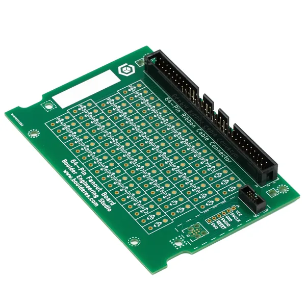
- Signal fanout boards
Also available: machined nests, fanout debug and expansion boards, tamper-resistant construction, enhanced chassis grounding, and auxiliary benchtop housings. We also design custom accessories, and the frame works as a base for fixtures you build yourself.
What documentation is included?
The base frame comes with the BT201 datasheet, covering mounting points, overall dimensions, recommended hardware, and recommended accessory configurations.
Documentation for a custom fixture depends on what it includes, but typically covers:
- Maintenance guides and replacement walkthroughs for wear parts such as pins
- Operator documentation for the software interface
- Engineering documentation for the software architecture, for teams customizing or extending their tests
How many cycles does a fixture last?
The frame is rated for 2,000,000+ cycles, with a maintenance interval of 250,000 cycles. Maintenance is a gas strut replacement, done in the field in under 10 minutes.
That rating covers the mechanical frame only. Pin life depends on the pins and the configuration, so we quote it per fixture. Pins can typically be replaced or refurbished without taking the fixture apart.
Can I update my fixture?
Yes. Fixture software runs in containers, and the eLink connectivity client handles configuration management, update coordination, and cloud sync across your fixtures. Updates to the operator interface and test software can be pushed with or without an operator at the station.
What do I do if I need to change a test?
Test limits and settings can be changed per fixture, in configuration files or remotely from a browser, without touching the test sequence.
What are the frame's dimensions?
Closed, Frame 01 Gen 2 (BT201) measures 300 × 270 × 254 mm and weighs 5.4 kg. The available DUT area is 230 × 140 × 35 mm, with a 290 × 260 × 63.5 mm mounting area for boards underneath. Full dimensions are in the BT201 datasheet.
Are there per-seat software license fees?
No. eLink has no per-seat programming license fees. The software is licensed per fixture under the eLink software license agreement. We keep ownership of the eLink platform, framework, and standard modules, and ownership of work written for your program follows your statement of work.
Which test instruments are supported?
The driver library includes the Rigol DS1054Z oscilloscope, Siglent SDM3055 and SDM3045 bench multimeters, the B&K Precision 1900B programmable supply, addressable LED indicators, and UART connections for DUT command shells and JSON-RPC firmware. Other instruments are integrated as part of the design package.
What else can you help with?
Around the fixture itself, we develop DUT test firmware on Zephyr RTOS, write drivers for accessories and new interfaces, build APIs to connect fixtures to your other tools, assess designs for manufacturability and testability, and support reshoring.
Frame 01 Gen 2 gallery
Download the BT201 frame datasheet (PDF)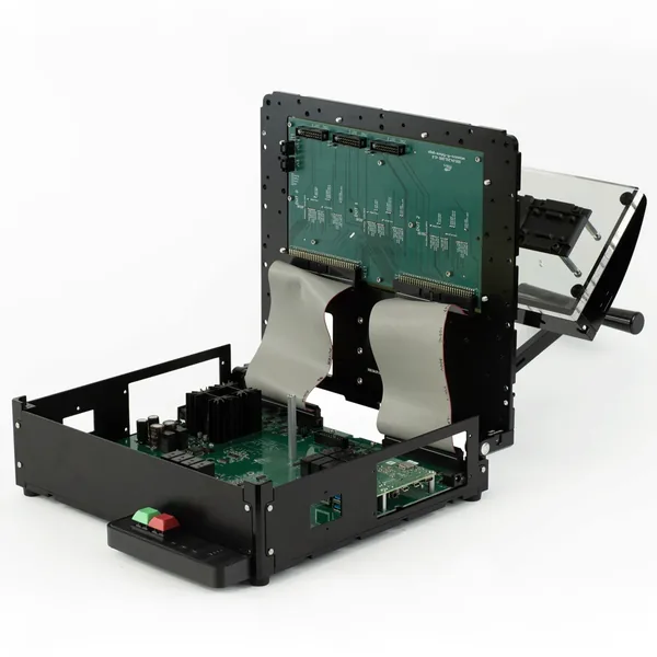
Start a fixture program
Tell us about your DUT, what it needs to be tested for, and your timeline. We will put together a plan and a quote.
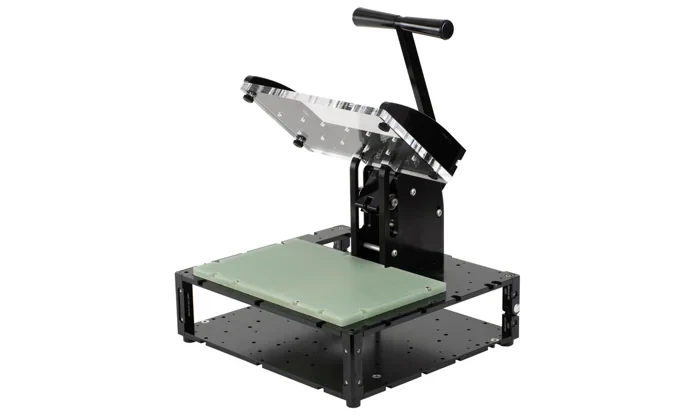
Base fixture frame: BT201-F50-00A
Base open frame with a blank pogo plate and acrylic top. Typically ships within 1 business day.